We simplify complex systems with clear, professional software diagrams. Using Lucidchart, Draw.io, and Visio, we create flowcharts, ERDs, UML, and architecture visuals that streamline team collaboration, accelerate development, and improve communication with stakeholders.
Use Case
Restaurant Management
Overview:
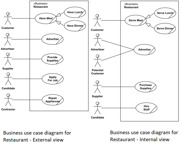
The Restaurant Management Use Case Diagram outlines the functional interactions between external business actors (such as customers and suppliers) and internal systems within a restaurant. It is split into two perspectives External View and Internal View—to effectively model service flow and business processes. This diagram is essential for system analysts, restaurant tech consultants, and developers planning to automate restaurant operations.
External Business View:
This portion of the diagram illustrates how outside entities interact with the restaurant. Primary actors
include:
- Customer – places orders, books reservations, and provides feedback.
- Supplier – delivers ingredients and receives orders.
- Delivery Partner – interacts for food delivery and logistics.
Each actor is connected to business use cases that fulfill their respective goals, such as Place
Order, Book Table, or Track Delivery.
Internal Business View:
The internal view reveals core operations managed within the restaurant system:
- Order Processing – manages dine-in, takeaway, and online orders.
- Inventory Management – handles stock levels and restocking requests.
- Kitchen Workflow – processes order queue and meal preparation.
- Billing System – generates bills, handles payments, and applies discounts.
- Feedback System – collects customer reviews for quality assurance.
Key Features:
- Actor-Based Design: Clearly separates user interactions by role.
- Service Breakdown: Modular representation of processes such as order placement, kitchen
handling, and billing. - Scalability: Can be extended to support loyalty programs, franchise modules, or mobile app integration.
How It Works:
A customer places an order via a front-end system (POS or mobile app). The request is routed through the kitchen module. Simultaneously, inventory levels are checked and updated. Upon order completion, the billing system is triggered, and customer feedback is collected post-meal. The restaurant’s internal
system also ensures that any inventory shortages prompt automated supplier requests.
Benefits:
- Streamlined Operations: Visualizes process flow, aiding in automation and system design.
- Improved Communication: Bridges understanding between business stakeholders and
developers. - Efficiency Insights: Identifies process bottlenecks and optimization areas.
Technologies Used:
- UML (Unified Modeling Language)
- Tools: Lucidchart, Draw.io, Visual Paradigm, or Rational Rose
Point of Sales Terminal
Overview:
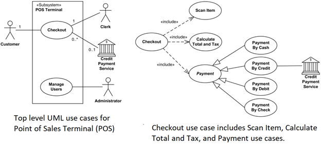
The Point of Sale (POS) Terminal Use Case Diagram illustrates how various actors interact with the POS system during a retail transaction. This system manages the entire checkout process—from scanning items to processing payments—and ensures streamlined operations at retail counters. This diagram is essential for developers building retail software, business analysts, and retail managers aiming to modernize store operations.
Primary Actors:
- Customer – shops for items and initiates the checkout process.
- Clerk (Cashier) – operates the POS system, scans items, and facilitates payment.
- Credit Payment Service – handles electronic payment authorization and
processing.
Core Use Cases:
- Scan Items: Items are scanned using a barcode scanner, and their prices are
retrieved from the product database. - Calculate Total and Taxes: The system calculates the subtotal, applies relevant
taxes, and shows the final amount due. - Process Payment: Payment may be done through various methods—cash, credit
card, debit card, or check. - Print Receipt: Generates and prints the receipt after payment confirmation.
Relationships and Design Concepts:
- Include Relationships: The Checkout use case includes scanning, calculating, and payment handling to break down responsibilities.
- Multiplicity Notations:
o A Customer must be involved in a checkout (1..1).
o A Clerk participates in one checkout at a time (1).
o A Credit Payment Service may be involved in multiple checkouts
simultaneously (0..*), and is optional depending on the payment type (0..1). - Generalization in Payment Use Case: Represents that only one payment method—cash, credit, debit, or check—is used per transaction. This enforces logical
exclusivity and simplifies the flow.
Features:
- Multi-Actor Coordination: Synchronizes the roles of customer, cashier, and
payment service. - Real-Time Totaling: Enables instant calculation of pricing and discounts.
- Flexible Payment Options: Supports multiple payment types using inheritance and
inclusion relationships. - Error Handling: Not explicitly shown but implied—missing payments, invalid cards, or scanning failures would be additional exceptions in a complete system.
How It Works:
The customer brings items to the checkout terminal. The clerk scans each item, prompting the system to compute the running total. When all items are scanned, the customer selects a payment method. If electronic payment is chosen, the system connects with the credit payment service. Once approved, a receipt is printed, and the checkout session ends. Inventory updates and sales logging are performed in the background.
Benefits:
- Efficient Checkout: Minimizes transaction time and reduces errors.
- Integrated Systems: Facilitates inventory updates and sales tracking.
- Scalability: Can be extended to self-checkout kiosks or mobile POS systems.
Technologies Used:
- UML for modeling
- Tools: Visual Paradigm, Lucidchart, StarUML, or Enterprise Architect
- POS software: Vend, Square, Lightspeed (integration targets)
Workflow
Scheduled Workflow
Overview:
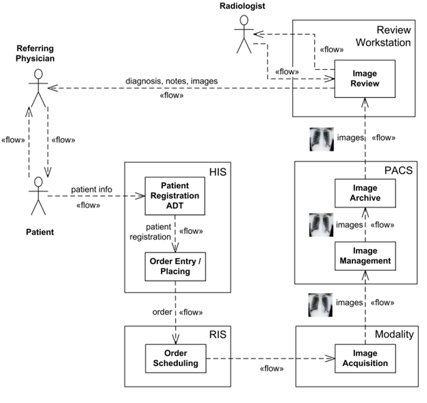
The Scheduled Workflow Information Flow Diagram models the exchange of
information across healthcare systems during radiology procedures. Based on the IHE (Integrating the Healthcare Enterprise) Radiology Technical Framework, this diagram visualizes how patient, order, and imaging data flow through a healthcare ecosystem. It is crucial for healthcare IT specialists, radiology system integrators, and HL7 interface developers working with HIS/RIS/PACS systems.
Purpose:
To demonstrate the interconnected processes involved in:
- Patient registration
- Radiology exam ordering
- Scheduling
- Image acquisition
- Image storage
- Image viewing
Key Components:
1. ADT / Patient Registration System: Manages patient demographic and visit data.
2. Hospital Information System (HIS): Coordinates administrative and clinical
workflows.
3. Radiology Information System (RIS): Handles scheduling, resource allocation,
and reporting for radiology departments.
4. Picture Archiving and Communication System (PACS): Stores and manages
digital medical images.
5. Imaging Acquisition Modality (e.g., CT, MRI): Captures radiographic images
during diagnostic exams.
Information Flows:
- Patient Registration → HIS/RIS: ADT sends patient data to HIS and RIS, ensuring synchronized demographic details.
- HIS → RIS: Orders for radiology exams are created and transmitted for scheduling.
- RIS → Modality: Schedules are pushed to the imaging system, preparing it for exam
execution. - Modality → PACS: After image acquisition, data is transferred to PACS for archival and access.
- PACS → Viewing Workstations: Radiologists and physicians retrieve and analyze the imaging data.
Features:
- Standards-Based Integration: Uses HL7 for patient and order data; DICOM for image transmission.
- Process Synchronization: Ensures exam requests and image delivery are logically and temporally aligned.
- Automation-Friendly: Minimizes manual intervention by synchronizing system
tasks.
How It Works:
A patient registers at the hospital, triggering the ADT system to send their information to HIS and RIS. A physician places an imaging order in HIS, which RIS picks up and schedules based on availability. The imaging modality receives the scheduled order details and captures the required scans. These images are then stored in PACS and become accessible for interpretation. This entire flow is bidirectional, with acknowledgments and updates sent between systems to ensure data consistency.
Use Cases:
- Hospital radiology departments
- Teleradiology networks
- Diagnostic imaging centers
- Cross-institutional healthcare data integration
Benefits:
- Improved Patient Safety: Reduces duplication and errors by centralizing patient and exam data.
- Operational Efficiency: Automates data sharing between departments, reducing delays.
- Enhanced Diagnostic Accuracy: Enables real-time access to high-quality images and associated data.
Technologies Used:
- UML 2.x for diagramming
- HL7 v2.x for clinical messaging
- DICOM for imaging data
- Integration tools: Mirth Connect, Orion Health, or InterSystems Ensemble
Abstract Factory Pattern
Overview:
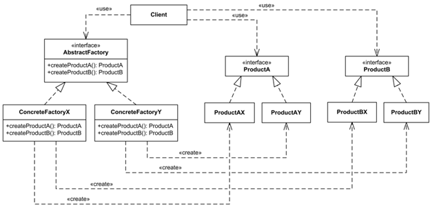
The Abstract Factory is a creational design pattern in software engineering that provides a blueprint for creating families of related or dependent objects without specifying their concrete classes. This UML class diagram showcases how abstract factories encapsulate object creation, promoting modular, flexible, and decoupled system architecture. It is ideal for developers designing scalable systems, frameworks, and libraries where the product family may vary but its structure remains consistent.
Purpose:
To create object families that work well together, while hiding the creation logic from the client. This is particularly useful in systems where multiple configurations or UI themes exist (e.g., light/dark UI factories).
Key Components:
1. AbstractFactory (Interface): Declares a set of methods for creating abstract
product objects.
2. ConcreteFactoryA / ConcreteFactoryB: Implementations of the AbstractFactory
that create specific product variants (e.g., GUI components for Windows vs macOS).
3. AbstractProductA / AbstractProductB: Interfaces for a family of products (e.g.,
Button, Textbox).
4. ConcreteProductA1 / A2 and B1 / B2: Actual implementations that belong to
families (e.g., WinButton vs MacButton).
5. Client: Uses only the abstract interfaces and is decoupled from specific factory or product implementations.
Features:
- Encapsulation of Object Creation: The client does not need to know the exact class of object that will be created.
- Product Families: Enables consistent product combinations.
- Decoupled Design: Changes to product implementations or families do not impact client code.
- Extensibility: New families can be introduced with minimal changes.
How It Works:
The client creates an instance of a concrete factory (e.g., WinFactory or MacFactory) using the abstract factory interface. The factory then returns the appropriate concrete product instances that conform to the defined abstract product interfaces. The client remains unaware of the specific types and works only with interfaces, promoting low coupling and high cohesion.
Example Use Case:
In a GUI toolkit:
- AbstractFactory → WidgetFactory
- AbstractProductA → Button, AbstractProductB → TextBox
- ConcreteFactoryA → WindowsWidgetFactory, ConcreteFactoryB →
MacWidgetFactory - Client code renders UI using whichever factory is injected.
Benefits:
- Consistency: Ensures that components from the same family are used together, avoiding UI or logic mismatches.
- Scalability: New product families can be added without changing existing code.
- Testability: Mocks or stubs of factories and products can be injected for unit testing.
Technologies/Tools Used:
- UML Tools: StarUML, Visual Paradigm, PlantUML
- Languages: Java, C#, C++, Python (commonly use this pattern)
- Framework Examples: Java Swing Look-and-Feel, .NET Abstract Factories, Android Themes
UML
Library Domain Model
Overview:
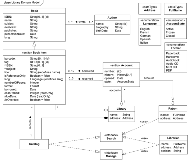
The Library Domain Model class diagram captures the core structure, entities, and relationships involved in a Library Management System (LMS), also known as an Integrated Library System (ILS). This domain-level representation is critical during the analysis and early design phase, helping stakeholders understand how key elements such as books, patrons, cataloging, and borrowing rules interact in a structured and scalable manner.
Purpose:
To provide a conceptual blueprint that illustrates classes, attributes, and associations governing the functionality of a modern library system, laying the foundation for implementation.
Key Classes & Attributes:
1. LibraryItem (Superclass): Represents all physical and digital resources. Attributes include itemID, barcode, title, and type.
2. Book (Subclass): Inherits from LibraryItem. Adds ISBN, author, subject.
3. User / Patron: Represents a library member. Attributes include userID, name, membershipType, and contactDetails.
4. Loan: Represents a borrowing transaction. Attributes: loanPeriod, dueDate, isOverdue.
5. LibraryCatalog: Interface to search, browse, and access library materials.
6. Reservation: Represents held or requested items. Associates users and resources with reservation timestamps.
Inheritance and Redefinitions:
- Book inherits attributes such as ISBN and subject from LibraryItem.
- Redefined attributes such as lang (language) transition from simple String to an enumerated Language class for better type control.
Derived Attributes:
- dueDate is computed based on the borrowing date and loan policy.
- isOverdue is automatically calculated based on the current date and the due date.
Features:
- Barcode & RFID Support: Items have barcodes or RFID tags for identification and automation.
- Dynamic Loan Policies: Vary loan periods by patron type (e.g., students, faculty, public users).
- Reservation Mechanism: Patrons can reserve books; the system manages availability and queuing.
Features:
- Barcode & RFID Support: Items have barcodes or RFID tags for identification and automation.
- Dynamic Loan Policies: Vary loan periods by patron type (e.g., students, faculty, public users).
- Reservation Mechanism: Patrons can reserve books; the system manages availability and queuing.
- Catalog Interface: Enables efficient search based on author, title, or subject.
How It Works:
A user searches the catalog to locate an item. If available, they borrow it, initiating a loan object tied to the user and item. The system tracks the due date and calculates whether the book is overdue. If unavailable, users can place a reservation. Librarians manage item check-ins/check-outs via barcode or RFID scanning, and all interactions are recorded in the system.
Use Cases:
- Public libraries
- School and university libraries
- Corporate document management
- Digital libraries and eBook systems
Benefits:
- Organized Domain Structure: Offers clarity on system behavior and relationships.
- Supports Automation: Barcode and RFID-ready design.
- Flexible Rule Definitions: Accommodates different borrowing policies for diverse patrons.
- Extensible: Can be enhanced to support multimedia content, fines, or inter-library loans.
Technologies/Tools Used:
- UML Tools: Lucidchart, Visual Paradigm, PlantUML
- Implementation: Java, Python, PHP with frameworks like Koha or Evergreen ILS
- Standards: MARC21 (for cataloging), Z39.50 (for catalog interoperability)
Sentinel HASP Licensing Domain
Overview:
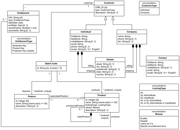
The Sentinel HASP Licensing Domain Class Diagram provides a structured view of the key entities and relationships involved in software protection and license management using the SafeNet Sentinel HASP system. This class diagram is a crucial tool for software vendors integrating secure licensing mechanisms, helping them manage features, entitlements, product versions, and digital rights efficiently.
Purpose:
To model the software licensing domain as managed by Sentinel HASP, enabling software developers and vendors to structure their license-based products with clarity and security compliance.
Key Classes & Attributes:
1. VendorKey:
Attributes: vendorCode, batchCode
Purpose: Identifies and authenticates the software vendor.
2. BatchCode:
Unique 5-character identifier assigned to a vendor; embedded in protection keys.
3. Feature:
Attributes: featureID, featureName, associatedBatchCode
Represents a specific capability or module within a software product.
4. Product:
Attributes: productName, lockingType, batchCode
Represents a complete software application or package.
5. BaseProduct (Superclass):
Contains common attributes such as memory layout, licensing type, and feature mappings.
6. ProvisionalProduct (Subclass):
A variant of BaseProduct designed for limited or trial use.
7. Entitlement:
Represents a license order or allocation linking specific products and features to a customer or distributor.
Relationships:
- Product ↔ Feature: Each product includes multiple features; features belong to one product batch.
- Product → BaseProduct: Inheritance relationship that allows reusability and modular licensing.
- ProvisionalProduct → Product: Inherits structure but supports temporary distribution (e.g., trials or demos).
- Entitlement → Product(s): Orders are fulfilled via entitlements that reference one or more licensed products.
Features:
- Batch-Based Licensing: All entities tie back to a unique batch code to ensure traceability.
- Modular Design: Products can be composed of multiple independently licensable features.
- Flexible Product Variants: Supports full, trial, and provisional licenses with varying rules and protections.
- Locking Types: Customizable options for binding licenses to specific hardware, network, or usage models.
How It Works:
A software vendor purchases a License Development Kit (LDK) and receives a unique vendor key. This key is used to generate protection keys and associate them with batch codes. Products are defined by the vendor, each containing features that can be activated or restricted via entitlements. When customers purchase software, entitlements are issued, referencing the appropriate products and features. Licensing enforcement occurs via hardware or software-based keys using the Sentinel runtime.
Use Cases:
- Commercial software products with modular features
- SaaS or downloadable trial software
- Licensing-as-a-Service platforms
- High-security enterprise software distribution
Benefits:
- IP Protection: Prevents unauthorized use or duplication of software.
- Revenue Optimization: Enables feature-based pricing and flexible licensing tiers.
- Vendor Control: Centralizes license and feature management.
- Scalability: Supports thousands of customers and product variants with minimal code duplication.
Technologies/Tools Used:
- UML Modeling Tools: StarUML, Enterprise Architect
- Sentinel Tools: Sentinel EMS, Sentinel Admin Control Center, Sentinel License Manager
- Integration: APIs available in C/C++, Java, .NET
Sequence
Sequence Diagram of an Online Exam System
Overview:
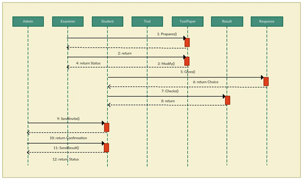
The Online Exam System Sequence Diagram visually represents the chronological interaction between users and system components during an online examination session. It captures the flow of operations, from user authentication to exam submission and result processing. This diagram is vital for system architects, e-learning developers, and QA engineers designing secure, interactive assessment platforms.
Purpose:
To model the step-by-step communication between actors (students and administrators) and system modules during an exam cycle—ensuring clarity in user interaction, back-end logic, and system responsibilities.
Actors:
1. Student: The end-user who logs in, takes the exam, and submits answers.
2. System (Exam Engine): Handles the exam logic, question delivery, timer control, and submission.
3. Database: Stores exam data, user credentials, responses, and results.
4. Admin (optional): Sets up the exam, configures time limits, and reviews results post-exam.
Key Interactions:
1. Login & Authentication:
- Student sends login credentials.
- System validates against the database and grants access.
2. Exam Initialization:
- System retrieves exam questions and timer settings from the database.
- Displays the first question to the student.
3. Question Navigation & Answer Submission:
- Student answers questions one by one.
- Each response is either auto-saved or stored upon exam completion.
4. Timer Management:
- System tracks remaining time.
- Automatically submits the exam upon expiration if the student hasn’t already.
5. Result Processing:
- Submitted answers are evaluated.
- Results are stored in the database and optionally displayed or emailed to the student.
Features:
- Real-Time Interaction: Live timer and auto-save features ensure uninterrupted exam flow.
- Security Integration: Supports session validation to prevent impersonation or cheating.
- Auto Submission: Ensures timely conclusion even if the student forgets to submit.
- Flexible Grading: Can handle both objective (MCQs) and subjective responses.
How It Works:
After logging in, the student starts the exam session. The system delivers questions sequentially or all at once, while tracking the time. Students can navigate between questions, and answers are either saved dynamically or at the end. If the timer ends, the system auto-submits the exam. Upon submission, the system evaluates answers (in case of objective questions) and stores the results in the database.
questions) and stores the results in the database.
Use Cases:
- University online assessments
- Recruitment aptitude tests
- Certification and licensing exams
- Corporate training and evaluations
Benefits:
- Structured Flow: Ensures every exam follows a secure, repeatable process.
- Improved UX: Simplifies navigation for students under time pressure.
- Accountability: Ensures audit trails for every action, useful for dispute resolution.
- Easy Integration: Diagram aligns with modern LMS or e-learning systems.
Technologies/Tools Used:
- UML tools: Lucidchart, Draw.io, Visual Paradigm
- Backend: Java, PHP, Python with MySQL/PostgreSQL
- Frontend: Angular/React with exam timer and real-time sync capabilities
Sequence Diagram Example of a School
Management System
Overview:
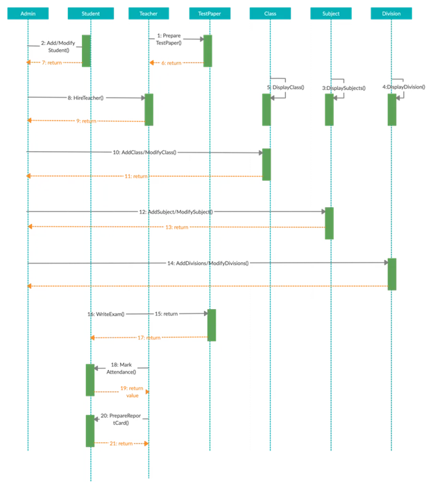
The School Management System Sequence Diagram outlines the sequential flow of interactions between administrators, teachers, students, and the central system as they perform academic and administrative operations. This model is essential for software developers, school IT consultants, and system integrators building modular educational platforms.
Purpose:
To visually represent how different actors communicate with the system components to perform tasks such as registration, attendance, grade management, and report generation—ensuring transparency and automation across school workflows.
Actors:
1. Admin: Manages user accounts, academic sessions, and course assignments.
2. Teacher: Marks attendance, uploads grades, and interacts with the academic records system.
3. Student: Views schedule, submits assignments, and checks performance.
4. School Management System (Core Platform): Orchestrates all backend operations.
5. Database: Stores user data, academic records, attendance logs, and system configurations.
Key Interactions:
1. User Authentication:
Actors (Admin/Teacher/Student) log in.
Credentials are verified by the system through the database.
2. Information Access:
Students view their timetables, assignments, or grades.
Teachers access class rosters and input attendance/grades.
3. Record Update:
Teachers submit attendance and assessment records.
The system updates student records and synchronizes grade reports.
4. Report Generation:
Admin generates student performance reports or attendance summaries.
System queries the database and compiles the results.
Features:
- Role-Based Access Control: Each actor accesses only the features relevant to their role.
- Centralized Data Handling: One platform handles all core school functions.
- Real-Time Sync: Data changes are reflected across user dashboards instantly.
- Modular Flow: Easily extendable to include fee management, messaging, or library systems.
How It Works:
Upon login, each actor sees a customized dashboard. Teachers can mark attendance, record grades, and post announcements. Students can view their academic progress, submit assignments, and receive updates. Admins monitor overall activity, configure classes, and access system-wide reports. All actions are logged and persisted in the database for future audits.
Use Cases:
- K-12 school management
- College and university portals
- Coaching institutes and training centers
- ERP systems in educational institutions
Benefits:
- Streamlined Workflow: Reduces manual paperwork and errors in records.
- Improved Communication: Keeps students, teachers, and administrators aligned.
- Accountability: Every action is traceable and time-stamped.
- Customization Friendly: Can support institution-specific academic structures.
Technologies/Tools Used:
- UML Modeling: Visual Paradigm, StarUML, Draw.io
- Backend: Java/.NET/PHP with MySQL, Oracle, or PostgreSQL
- Frontend: Web or mobile-based UI for multirole access
Example of an Option Combination Fragment
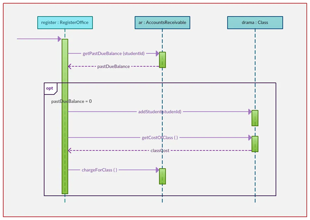
Overview:
An Option Combination Fragment in a sequence diagram is a type of interaction fragment that models a conditional branch in a system’s behavior—essentially an “if-then” logic. It defines an optional sequence of interactions that occur only if a specified condition is true. This construct is particularly useful in scenarios where an alternate path may or may not be taken, depending on runtime decisions or system states.
Purpose:
To demonstrate how optional behavior is incorporated into the dynamic flow of interactions between objects in a software system. This is essential for modeling functionalities such as additional verification steps, feature toggles, or conditional notifications.
Actors and Components:
- User: The primary actor who initiates the interaction.
- System (Client App): Manages user sessions and conditionally displays options.
- Authentication Server: Validates credentials and provides access control.
- OTP Verification Module (Optional): Triggered only if two-factor authentication is enabled.
Scenario – Optional Two-Factor Authentication during Login:
1. The user initiates the login process by entering their credentials.
2. The system sends these credentials to the authentication server.
3. If the credentials are valid, the system checks whether two-factor authentication (2FA) is enabled.
4. [Option Fragment Begins] Condition: 2FA Enabled == true
- The OTP module prompts the user to enter a one-time password.
- The user enters the OTP, which is then verified by the server.
- If successful, access is granted. [Option Fragment Ends]
5. If 2FA is not enabled, the system directly grants access.
Diagram Features:
- The option fragment is enclosed in a rectangular frame with the label opt and the condition written at the top-left.
- The interactions within the fragment only occur if the condition evaluates to true.
- Outside the frame, regular interactions proceed unaffected by the conditional flow.
Benefits:
- Clear Modeling of Optional Logic: Ensures that designers and developers understand which behaviors are not guaranteed to execute.
- Improved System Documentation: Helps business analysts visualize decision-based flows.
- Scalability: Useful in scenarios where features may be toggled on/off (e.g., trial features, add-on services).
Use Cases:
- Optional OTP verification
- Discount eligibility checks
- Displaying personalized content
- Conditional pop-up messages
Technologies/Tools Used:
- UML 2.0 and above
- Tools: Lucidchart, Visual Paradigm, Draw.io, StarUML
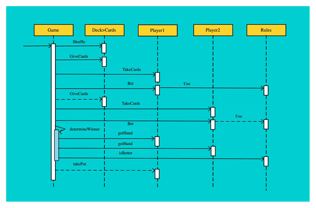
Sequence Diagram Example of a Card Game
Overview:
The Card Game Sequence Diagram models the turn-based interaction flow in a digital card game environment. It captures how players interact with the game engine, deck manager, and user interface to draw cards, play moves, and determine game outcomes. This diagram is essential for game developers, interaction designers, and system architects building card-based or board-style gaming applications.
Purpose:
To represent the sequence of actions and communications among game components during a player’s turn, facilitating clear design of game logic, state transitions, and rule enforcement.
Actors and Components:
1. Player: Human or AI-controlled user who participates in the game.
2. Game Engine: Core logic processor that validates actions, maintains game state, and determines outcomes.
3. Deck Manager: Manages the draw and discard pile, shuffling, and card distribution.
4. UI (User Interface): Visual layer that allows the player to interact with the game.
5. Scoreboard (optional): Tracks and displays points, wins, or statuses.
Key Interactions:
1. Start Game:
- Player initiates the game via the UI.
- Game Engine initializes the game state and prompts the Deck Manager to shuffle and distribute cards.
2. Player Turn Begins:
- The system requests the next move from the player.
- Player selects and plays a card via the UI.
3. Card Validation:
- Game Engine checks if the move is legal based on rules (e.g., suit match, power cards).
- If valid, the move is processed; otherwise, an error message is shown.
4. Game State Update:
- Deck Manager updates the draw/discard piles.
- Game Engine updates player states (e.g., hand size, scores).
5. Turn Rotation:
- Game Engine switches turn to the next player and repeats the sequence.
Features:
- Turn-Based Control Flow: Each player’s action is executed sequentially with validation.
- Deck Abstraction: Encapsulates card draw, shuffle, and pile management logic.
- Rule Enforcement Engine: Ensures fair play by validating every move.
- UI Feedback Loop: Provides instant visual and textual updates to players.
How It Works:
Once the game is launched, the deck is shuffled and cards are dealt. During each player’s turn, they interact with the UI to make a move. The selected card is passed to the game engine, which checks if the move is valid. If so, the deck is updated and the game state reflects the change (e.g., points, remaining cards). Turns alternate until a win condition is met.
Use Cases:
- Traditional games (Uno, Poker, Rummy, Solitaire)
- Multiplayer online card games
- Educational or logic-based card games
- AI simulation or training tools
Benefits:
- Clear Game Logic Design: Simplifies game mechanics and rule integration.
- Extendable Architecture: Easy to support power cards, special rules, or multiplayer sync.
- Enhanced Debugging: Pinpoints action sequences during development or testing.
- Improved UX Planning: Helps align gameplay flow with UI behavior.
Technologies/Tools Used:
- UML Tools: Lucidchart, Visual Paradigm, Draw.io
- Game Development: Unity (C#), Godot (GDScript), HTML5/JavaScript
Multiplayer Support: WebSockets, Firebase, Photon Engine
Sequence Diagram Example of an Online
Movie Ticket Booking System

Overview:
The sequence diagram for an online movie ticket booking system captures the detailed flow of interaction between users, interfaces, back-end services, and third-party components like payment gateways. This model is critical for understanding the time-based communication and ensuring seamless booking, confirmation, and ticket generation processes.
Purpose:
To represent the sequential communication that occurs when a user browses available movies, selects seats, processes payment, and receives ticket confirmation. It aids developers and stakeholders in designing robust, real-time movie booking platforms.
Actors:
- User: Initiates the ticket booking process.
- Movie Booking UI: Front-end interface.
- Booking Engine (System): Core logic for availability, pricing, and booking.
- Payment Gateway: Third-party service for transaction processing.
- Database: Stores all booking, movie, and transaction data.
Sequence Flow:
1. The user logs into the movie booking application or website.
2. The UI displays the list of movies, showtimes, and locations.
3. The user selects a specific movie, date, and showtime.
4. The UI sends a request to the booking engine for seat availability.
5. The system queries the database and returns the available seats.
6. The user selects seats and proceeds to checkout.
7. The total price is calculated based on seat type, quantity, and location.
8. The payment request is sent to the payment gateway.
9. Upon successful payment, a transaction confirmation is returned.
10. The booking engine updates the database with the confirmed booking.
11. A ticket is generated and displayed or emailed to the user.
Features:
- Real-time seat availability checks
- Price computation logic with seat types (VIP, standard)
- Secure transaction handling
- Instant ticket generation and email confirmation
How It Works:
The user interacts primarily with the UI, while the system coordinates behind the scenes. The booking engine validates input, checks business rules, and ensures concurrency control on seat selection. Payment interactions are secured using SSL and tokenization.
Benefits:
- Ensures high availability and consistent user experience
- Prevents double bookings through synchronized database updates
- Helps teams define modules such as Payment, Ticketing, and Booking independently
Tools & Tech Stack:
- UML 2.x modeling
- Payment APIs (Stripe, Razorpay)
- Frontend: React/Vue
- Backend: Java, Node.js
- Database: MySQL/PostgreSQL
ERD
Hotel Management
Overview:
The Entity Relationship Diagram (ERD) for a Hotel Management System provides a comprehensive view of how data entities are structured and interconnected to support core operations like room booking, customer management, and payment tracking. This model is vital for backend developers, system architects, and hospitality software providers aiming to build efficient, scalable hotel automation systems.
Purpose:
To model the data structure that supports room reservations, customer profiles, service management, billing, and hotel inventory tracking—all in one integrated database system.
Entities and Their Attributes:
- Hotel: hotel_ID (PK), hotel_name, hotel_type, hotel_rent, hotel_description
- Room: room_ID (PK), room_type, availability, price, hotel_ID (FK)
- Customer: customer_ID (PK), customer_name, customer_pass, customer_email, customer_mobile, customer_address
- Booking: booking_ID (PK), booking_type, booking_description, customer_ID (FK), room_ID (FK), checkin_date, checkout_date
- Payment: payment_ID (PK), booking_ID (FK), payment_description, payment_date, payment_amount
- Service: service_ID (PK), service_description, service_cost, room_ID (FK)
Relationships:
- A hotel owns multiple rooms (1-to-many).
- A customer can have multiple bookings (1-to-many).
- A booking is linked to a room and a customer (many-to-1).
- A payment is associated with one booking (1-to-1).
- A room can have multiple services (1-to-many).
Features:
- Maintains accurate booking and availability status.
- Tracks financial transactions through linked payment records.
- Supports add-on services (e.g., laundry, room service).
- Easily expandable to include staff, feedback, or loyalty programs.
Benefits:
- Helps automate check-in and check-out processes.
- Improves customer service with detailed profiles and booking history.
- Ensures better resource allocation and room management.
- Facilitates reporting and accounting tasks for hotel administration.
Technologies/Tools Used:
- Database Design: MySQL, Oracle, SQL Server
- UML ERD Tools: Lucidchart, Draw.io, Visual Paradigm
- Programming Integration: Java, PHP, Python

University DataBase
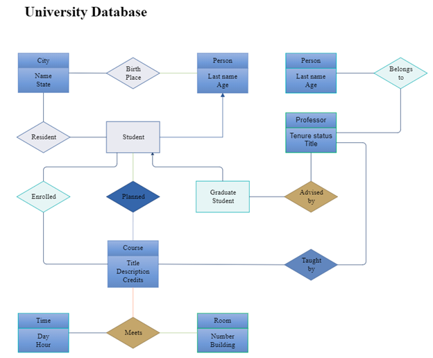
Overview:
A University Database ERD is a logical data model that represents academic and administrative elements of a university system. It is useful for managing student information, course registrations, faculty data, and academic performance efficiently.
Purpose:
To create a normalized structure that supports academic workflows, such as course enrollment, grading, and faculty assignments, while ensuring data consistency and easy retrieval.
Entities and Their Attributes:
- Student: student_ID (PK), name, age, birthplace, birthday, major
- Course: course_ID (PK), title, description, credit_hours, department
- Professor: professor_ID (PK), name, age, tenure_status, job_title
- Enrollment: enrollment_ID (PK), student_ID (FK), course_ID (FK), semester, grade
- Teaches: teaches_ID (PK), professor_ID (FK), course_ID (FK), semester
Relationships:
- A student enrolls in many courses (many-to-many via Enrollment).
- A professor teaches many courses (1-to-many or many-to-many via Teaches).
- Each course may have multiple students and professors (depending on department structure).
Features:
- Captures performance and history of each student.
- Supports semester-wise course offerings.
- Ensures academic auditing with complete faculty-course linkage.
- Flexible enough to support attendance, schedules, and exam management.
Benefits:
- Centralized academic record-keeping
- Enables performance analytics and curriculum optimization
- Easy integration into portals and mobile apps
- Strong foundation for academic ERP systems
Technologies/Tools Used:
- ER Modeling Tools: StarUML, Visual Paradigm, MySQL Workbench
- Languages: Python (Flask/Django), Java (Spring Boot)
- Reporting: JasperReports, Crystal Reports
Library Management system
Overview:
The ERD for a Library Management System illustrates the structured relationships among books, members, and publishers, enabling efficient tracking of library inventory, membership data, and borrowing transactions. This model forms the backbone of digital and physical library systems and helps streamline lending operations, search functionalities, and overdue monitoring.
Purpose:
To create a logical data representation that manages books, tracks borrowers, supports cataloging by publisher, and handles lending and return activities—all essential for smooth library functioning.
Entities and Their Attributes:
- Book: book_ID (PK), title, author, price, availability, publisher_ID (FK)
- Publisher: publisher_ID (PK), publisher_name, publisher_address
- Member: member_ID (PK), member_name, member_type, member_address, member_date, expiry_date
- Loan: loan_ID (PK), book_ID (FK), member_ID (FK), issue_date, due_date, return_date, is_returned
Relationships:
- A member can borrow many books (1-to-many via Loan).
- A book is associated with one publisher, but a publisher can have many books (1-to-many).
- A loan represents a many-to-many relationship between books and members, with temporal tracking.
Key Functionalities:
- Track availability status (issued or available) of books.
- Store borrower history and automate due date alerts.
- Support search and classification by author, title, subject.
- Enable reservation systems and renewal workflows.
Features:
- Supports barcode or RFID tracking for quick operations.
- Categorizes members by type (student, staff, public).
- Includes automatic overdue detection and penalty logic.
- Easily scalable to include staff roles, digital resources, or inter-library loans.
Benefits:
- Efficient resource utilization with controlled lending.
- Reduces human error via automated tracking.
- Improves member experience with personalized dashboards.
- Enables analytics such as most borrowed books or active users.
Technologies/Tools Used:
- UML Tools: Visual Paradigm, Lucidchart, Draw.io
- Implementation: Koha ILS, Evergreen, or custom apps in PHP, Python, or Java
- Standards: MARC21 (cataloging), Z39.50 (library interoperability)

Online Shopping System
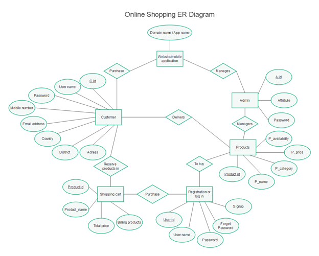
Overview:
The ERD for an Online Shopping System lays the foundation for building e-commerce platforms that manage products, customers, shopping carts, orders, and payments. This diagram is crucial for full-stack developers and system designers who aim to create intuitive, secure, and scalable online marketplaces.
Purpose:
To model how online shoppers interact with product listings, fill their carts, complete purchases, and communicate with platform administrators. It supports both B2C and B2B environments with flexible transaction structures.
Entities and Their Attributes:
- Customer: C_id (PK), username, password, email, mobile_number, country, district, address
- Product: product_ID (PK), P_name, P_category, P_price, P_availability
- Admin: A_id (PK), username, password
- ShoppingCart: cart_ID (PK), customer_ID (FK), total_price
- CartItem: item_ID (PK), cart_ID (FK), product_ID (FK), quantity
- Order: order_ID (PK), customer_ID (FK), order_date, total_amount, status
- Registration: reg_ID (PK), username, password, security_question, signup_date
Relationships:
- One customer can have multiple orders and one shopping cart.
- A shopping cart contains multiple cart items, each linked to a product.
- An admin manages products and customer-related issues.
- Orders are generated from cart contents and linked to customers.
System Behaviors:
- Customers browse products and add them to their shopping cart.
- During checkout, an order is created, and payment is processed.
- Admins oversee product listings, pricing, and stock levels.
- Customers can register, sign in, and recover their accounts via the registration entity.
Features:
- Real-time product stock updates
- Customer authentication and cart persistence
- Discount and promo code support
- Order history and status tracking
Benefits:
- Enables seamless shopping experience
- Reduces cart abandonment through saved sessions
- Supports admin-level product control and inventory management
- Designed for responsive web/mobile implementation
Technologies/Tools Used:
- UML Tools: StarUML, Lucidchart, MySQL Workbench
- Stack: MERN/MEAN, PHP+MySQL, Java (Spring Boot), or Django
- Integration: Stripe, PayPal, Razorpay for payment processing